I’m putting together my system in the HL15 finally and would appreciate some guidance with the power button. I’m using a H11SSL-NC motherboard and am not exactly sure in which arrangement I should plug the wires for the power switch in.
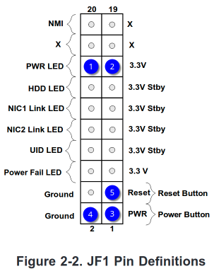
Should Power LED + go in 1, Power LED - in 2?
Should Power SW go with the arrow in 3 then 4? Or arrow in 3 then 5?
I know others have had difficulty with the power button pinout and even the button itself being wrong. In case you haven’t seen this yet, link below is to the button pinout provided by 45HomeLab in one such post.
A few posts above this one user @homelab has a very similar diagram to yours.
Referencing the blue circles; The power switch connects 3 & 4. It doesn’t matter which way round it goes. For the LED, if there is no guidance in the manual or on the board, just try it one way; if the LED doesn’t light, reverse the two; it won’t hurt anything if you get it wrong first.
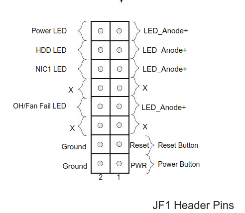
This is a common header on many Supermicro server and workstation boards including the one provided with the HL15 full build, and Supermicro chassis typically have a single corresponding front header plug. Below is a diagram from a different motherboard. Not all motherboards will use all features (eg, have dual NICs).
This one has 16 pins, not 20, but you get the idea, For the connections where polarity matters, the odd numbered pins of the header are + and the even numbered pins are -.