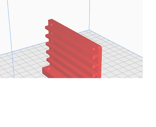
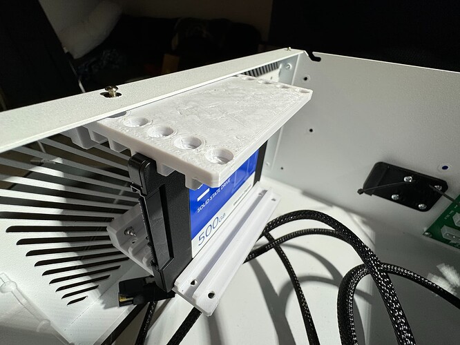
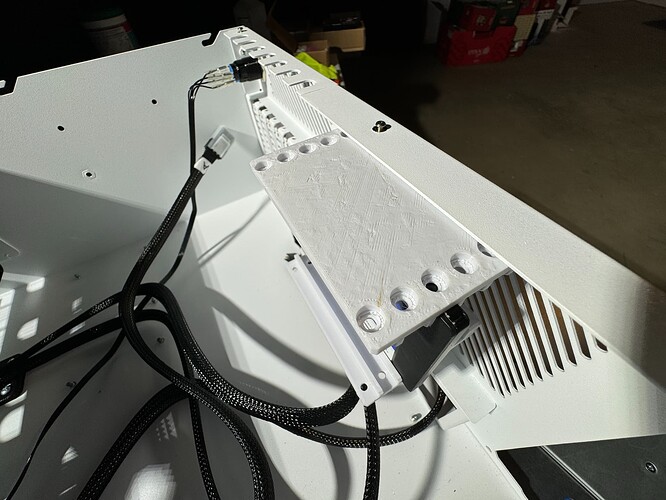
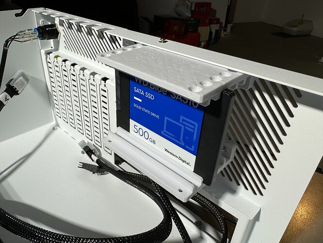
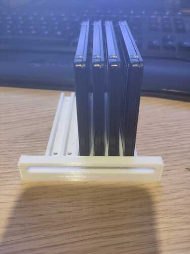
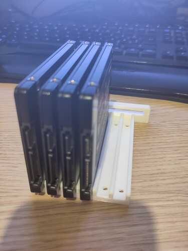
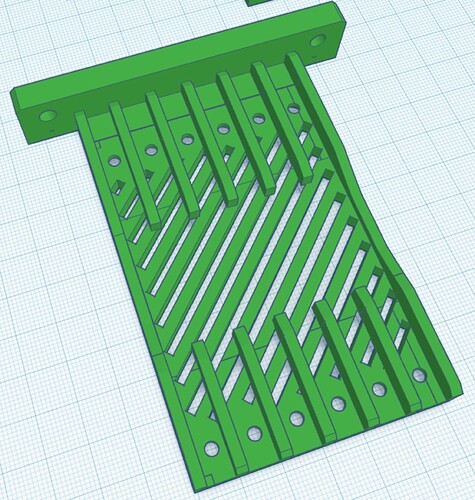
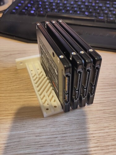
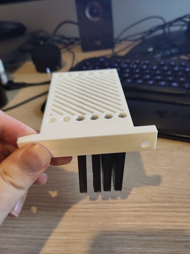
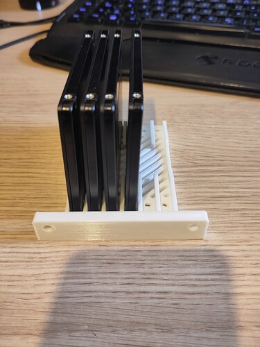
How do you position the 3d model on the 3d printer bed for printing ? Vertivaly on the narrow side or flat on the large side ?
That does look good!
Prototype A:
Not happy with the margins on that one for an possible fan, took 4 hours on cura “LowQuallity” preset plus TreeSupport.
Also not very happy with the mount system i imagined. May needs to be a bit bigger.
But this one does not require 2 parts and can hold the SSD’s as-is.
Looking good!
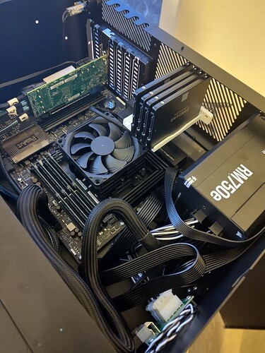
Make sure you test fit placement with cables.
![]()
Id be more worried about the overhang from each of the “slots” if you have the model vertically. You’ll have the easiest time with the orientation in your second picture. If you’re using the brass thread inserts, a little overhang in the holes there isn’t a big problem as you’ll heat up and sort of melt the insert into the hole anyway.
My poor Prusa MK3S+ decided it didn’t want to print anymore after a recent firmware upgrade (issues with the Revo Six hotend… ![]() )
)
I have a BambuLabs P1S (supposedly…) shipping any day now. Once I get my head around their slicer I’ll pop back in here to try and help.
Seriously, take the printer out of the box, load up the slicer - and just print. I got an 1Xc and that thing is a game changer. Their whole line is. Ender 3 is in a box waiting for my nephew to take. I tweak the odd setting for supports, infills etc. the rest is just “magic”.
Rev2 is just read to print ![]()
The distance is 1to1 taken from the original so that should not be that big of an issue. Can only really test when/if my HL15 gets here in December (hopefully)
Rev2 is printed
- Uses the original mounting holes
- Rotated 90°
- has 6 slots
- uses less material
- Ridged enough to support the SSDs a a single piece if mounted at the bottom:
Recommended to use a support blocker in the middle section (Printer should print those small overhangs just fine even without supports.
My MK3S+ was really reliable to be honest and felt about as magic once I had the first layer and z offset locked in. I’d run a manual re-calibration every few months if I made any changes to the hot end or what not.
Mainly it’s just going to be getting used to slicing for multicolor and what not as I purchased it with the AMS.
Can you shoot me a link for those inserts? I’ve been meaning to pick some up for a bit now.
This maybe a little off topice but how is everyone powering these additional drives? All 4 of the SATA/PATA plugs are used by the front 15 drives and fans.
Splitters I guess. I only use two of the leads coming from my PSU and split them into 4 which power the backplane. My PSU has one other SATA power connector left which I could use for more SSDs if needed.
If using splitters beware of the amperage/load concern. Fifteen drives in the front likely uses close to 20A and your 12V rails may not have a ton more headroom.
In each of my HL15 I’m adding 6x 6.4TB U.2 hanging off some MCIO ports and using a modified variant of this bracket and bought a PSU with this in mind!
All the connectors on the PSU are connected to that same 12v rail anyway so its all good.
I have an SSD that is 9mm so the 7mm is too small and 15 too large. Any change the design could be tweaked so I can download and print?
or
Can we get the CAD files so that we can modify the design?
This link was on this thread in the second post.
Reposting the URL here to printables: Printables
I had the same need so I worked with my sister to make a 9mm SSD Caddy by “remodeling” the STL from printables. I’ll send you a private message of the STL. I’m hoping to get those up on printables here soon.
It would be great to share the design back as other forum users can benefit (in the future).
