I plan on using an ASRock SIENAD8UD-2L2Q in an HL15.
As im not used to server hardware connector types i would like to have some advice on what data cable set i need to use to connect the backplane to the mainboard.
I read in the board spec about 2 MCIO. Could that be used to connect to the backplane?
I have no experience with MCIO, but yes that appears to be the way to connect SATA drives (or the backplane) to that board. You would need to buy two MCIO to SFF-8643 forward breakout cables something like this;
But double-check 74-pin MCIO is correct as there are apparently three sizes.
This isn’t a cable set 45HL offers directly AFAIK, so you’ll need to contact them (info@45homelab.com) for what your options would be in lieu. They may be able to special order them, they may give you a credit for no cables, you might have to pick a set of cables from the ones offered and resell them. Not huge, but cables are probably about $100 of the bundled HL15 cost.
Note that per the specs, this is only support for SATA drives. If you wanted to use SAS drives, you would need a separate HBA card.
Thanks for your reply. I now have an idea on how to go forward. First i’ll try to contact the support and will think about a next step after the response.
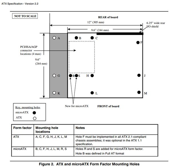
Unrelated to your question, and you may be aware of this; the motherboard area and standoff locations on the HL15 are mainly geared for ATX motherboards. The 10.5" depth for your board should be ok, but the HL15 chassis may not have all the MicroATX standoff locations. Specifically, referencing;
For B, R, and S it looks like your board uses B and R, whereas the HL15 just has a standoff for S per the CAD drawing (if I’m looking at it correctly). So, you might need to provide some additional support to the PCIe card area of the board to prevent flexing when installing and removing cards…
It may also be difficult to use the front-facing port by screw L. I assume that is one of the five MCIO ports, but I couldn’t find any manual for the motherboard online to confirm which two of the five ports are SATA-capable. There is some room under the mid-chassis fans, so depending on height, it’s possible that cable connector would slide under the fans, but you’d need to leave slack for it to be connected before installing and disconnected after removing the motherboard.
I don’t plan on adding a PCIe card unless i need to use an HBA. So the most strain on the board will be the CPU cooler and the MCIO cable. In addition i think i will use a plastic spacer to compensate flexing.
The missing online documentation is something that annoys me a lot. But welp, its not that uncommon in the server sector i assume. There are some zip files in stp format, but i don’t have a 3D CAD program.
About the connections and the hole L i found an image in this forum. From what i see, the cables should fit under the fan.
Watching the video at that thread, and going to where he installs his Asrock “Deep Micro-ATX” board (11:46), I think you’re fine for the standoff locations;